265BT41.0 Beam Tee (cut from UB)
Cut from AS/NZS 3679.1 UBGrade 300The 265BT41.0 is a beam tee (cut from a UB) to Cut from AS/NZS 3679.1 UB. It is 264 mm deep with a 209 mm wide flange, has a mass of 41.0 kg/m and a gross area of 5251 mm². Its major-axis second moment of area is Ix = 35.3 × 10⁶ mm⁴. It is cut from a 530UB82.0. Download its free DXF drawing (a true-scale CAD outline) below, or print the dimensioned drawing sheet.
Also written as: 265 BT 41.0, 265BT41, 265 BT 41
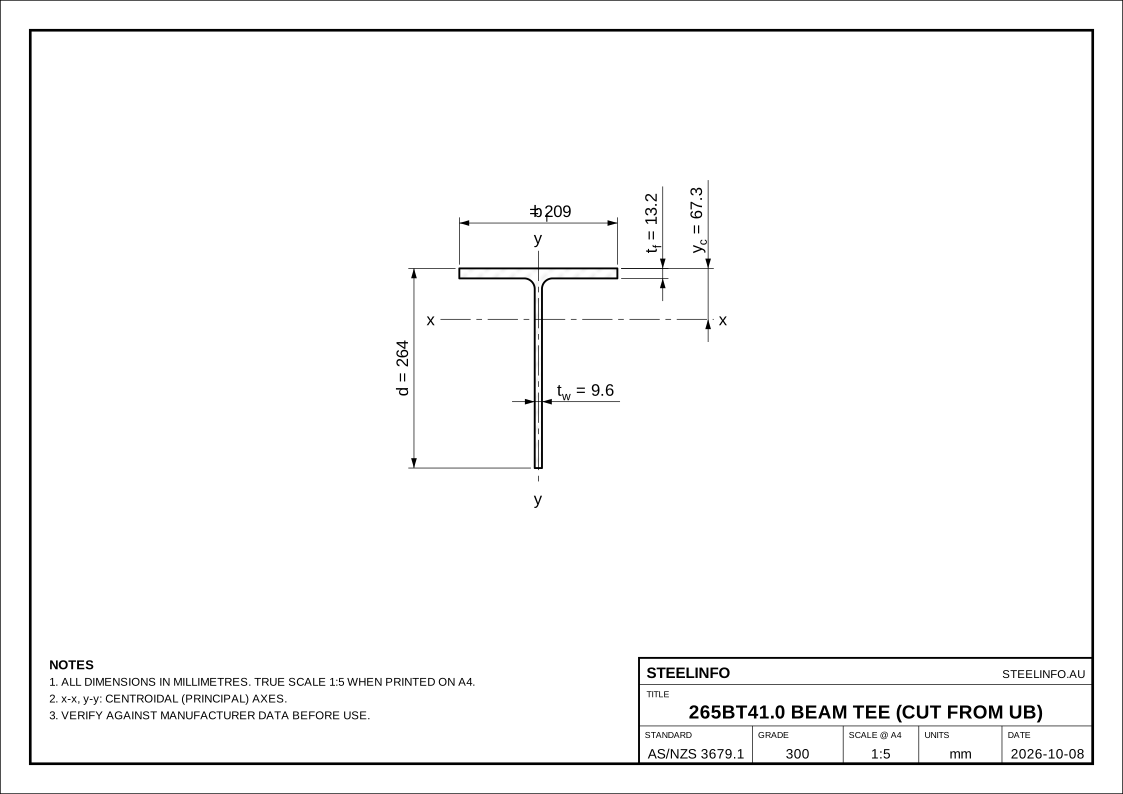
Open the drawing full size (pinch to zoom)
Dimensions
| Symbol | Property | Value | Unit |
|---|---|---|---|
| d | Depth of tee | 264 | mm |
| bf | Flange width | 209 | mm |
| tf | Flange thickness | 13.2 | mm |
| tw | Stem thickness | 9.6 | mm |
| r1 | Root radius | 14.0 | mm |
Section properties
| Symbol | Property | Value | Unit |
|---|---|---|---|
| m | Mass per metre (nominal) | 41.0 | kg/m |
| Ag | Gross cross-section area | 5251 | mm² |
| Ix | Second moment of area about x-axis | 35.3 | 10⁶ mm⁴ |
| Zx | Elastic section modulus, x-axis (stem tip) | 179 | 10³ mm³ |
| Zxf | Elastic section modulus, x-axis (flange) | 524 | 10³ mm³ |
| Sx | Plastic section modulus, x-axis | 320 | 10³ mm³ |
| rx | Radius of gyration, x-axis | 82.0 | mm |
| Iy | Second moment of area about y-axis | 10.1 | 10⁶ mm⁴ |
| Zy | Elastic section modulus, y-axis | 96.3 | 10³ mm³ |
| Sy | Plastic section modulus, y-axis | 151 | 10³ mm³ |
| ry | Radius of gyration, y-axis | 43.8 | mm |
| yc | Centroid from top of flange | 67.3 | mm |
| J | Torsion constant | 234 | 10³ mm⁴ |
| As | External surface area per metre | 0.934 | m²/m |
| As/t | External surface area per tonne | 22.8 | m²/t |
Axes: x-x (major) and y-y through the centroid. yc is measured from the top of the flange.
Design capacities to AS 4100
| Symbol | Property | Value | Unit |
|---|---|---|---|
| Steel grade | 300 (AS/NZS 3679.1) | ||
| fy | Yield stress used | 300 | MPa |
| fu | Tensile strength | 440 | MPa |
| kf | Form factor (Cl. 6.2.2) | 0.798 | |
| φNs | Section compression capacity (Cl. 6.2.1) | 1131 | kN |
| φNt | Tension capacity, gross section (Cl. 7.2, kt=1, An=Ag) | 1418 | kN |
| αb | Compression member section constant (Table 6.3.3) | 1 |
| Le (m) | φNcx (kN) | φNcy (kN) |
|---|---|---|
| 0.5 | 1131 | 1131 |
| 1 | 1131 | 1064 |
| 1.5 | 1098 | 977 |
| 2 | 1052 | 887 |
| 2.5 | 1006 | 797 |
| 3 | 959 | 711 |
| 3.5 | 911 | 629 |
| 4 | 863 | 555 |
| 5 | 767 | 432 |
| 6 | 677 | 339 |
| 7 | 593 | 270 |
| 8 | 518 | 219 |
| 9 | 453 | 180 |
| 10 | 397 | 151 |
| 12 | 308 | 109 |
φNc: Cl. 6.3.3, pin-ended effective length Le = keL, concentric load.
For restraint types, ktklkr and αm, use the lateral restraint calculator.
Instant check only. Effective lengths and moment modification factors must be determined by the designer in accordance with AS 4100 Cl. 4.6, 5.6.3 and 6.3.2. Not a substitute for a qualified engineer: see the disclaimer.
Other beam tees (bt)
Relevant Australian Standards
- AS/NZS 3679.1:2016 Structural steel – Part 1: Hot-rolled bars and sections
Specifies chemical composition, mechanical properties and tolerances for hot-rolled universal beams and columns, channels, angles, flats and bars in Grades 300 and 350. - AS 4100:2020 Steel structures
The Australian design Standard for steel members and connections. Covers section classification (Section 5), member moment capacity including lateral-torsional buckling (5.6), shear (5.11), axial compression (Section 6), tension (Section 7) and combined actions (Section 8). - AS/NZS 5131:2016 Structural steelwork – Fabrication and erection
Fabrication, erection, tolerances, inspection and construction categories (CC1–CC4) for structural steelwork.
See all Australian Standards for structural steel.
Properties are calculated from nominal dimensions, including root and toe radii, as described in notation & method. Mass is the nominal catalogue mass; the calculated mass at 7850 kg/m³ is 41.22 kg/m. Verify against current manufacturer literature before use in design. Spotted an error? Report it.